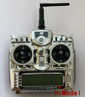
Jr Transmitter Manual
JR Propo Transmitters. JR radio systems are best known by passionate RC modelers for their precise response, intuitive programming and superior ergonomics. Picture File Date DL; RG831BP Operation Manual. File format: PDF. File size: 1.6MB. Mercury Operation Manual. File format: PDF. File size: 3.82MB. PCM10X Heli Transmitter. PCM10X Manual. JR Propo Trainer Cable. JR Propo Power Adapter. JR Propo Neck Strap. JR Propo Aluminum Case. 2x Keys for Aluminum Case.

Apv Pasteurizer Manual. • PCM9X II 9-CHANNEL COMPUTER RADIO SYSTEM Instruction Manual. • General Section. • Type Select Model Reset Modulation Transfer – Transfer the model to another transmitter or to DataSafe Transfer a model from the PCM9X II – (Transfer function) Transfer a model to the PCM9X II – (Transfer function) Stick Mode Stick Direction. • Servo Precautions General notes Aviation Regulations Daily Flight Checks Warranty Information General Section. • Section 1: Using this manual would normally be needed to set up a typical aircraft, 6 This Manual is divided into three specific sections: servo winged sailplane and helicopter respectively.
An Airplane, Sailplane and Helicopter. Explanation of the use and purpose of each feature is provided, followed by a labeled illustration of its In this manual you will find the specifications for the respective LCD display. • Section 3: Component Specifications Component Specifications Type Airplane System Name PCM9X II Transmitter Body NET-N239ES Receiver R900 Charger NEC-322AUS Airborne Battery 1100mah Servos 4 ea ES539 Accessories Deluxe Switch Servo Accessories Hex Wrench Instruction Manual Transmitter Specifications Type Airplane Model Number. • Servo Specifications Type ES-539 Torque 4.8kg.cm Speed 0.23 sec Weight 38 gm Size mm (L x W x H) 32.5 x 19 x 38.5 mm Ballbearing Motor Ferrite Airborne Battery Pack Specifications Type Airplane Model Number B1100 Voltage 4.8V Capacity 1100 mAH Size (in) (L x W x H) 2.24 x 0.53 x 1.70. • Beware of improper connections based on “color-coded” wire leads, as they do not apply in this instance.
You must make sure that the center pin of your JR transmitter is always connected to the negative voltage for correct polarity hookup. • PCM9X II Transmitter Features (Front) Antenna Neckstrap Attachment Flap Trim/Hover Pitch Trim Aux Trim/ Hover Throttle Trim Throttle Hold/Mix Switch Handle Rudder D/R / AUX4 Switch Trainer/Timer/ Snap Roll Switch Elevator D/R Flight Mode/ AUX4/AUX2 Switch Flap/AUX2 Switch Aileron D/R.
• PCM9X II Transmitter Features (Rear) RF Module Direct Servo Connection/ Trainer Lead Battery Cover CAUTION: THE BATTERY CONNECTION IS KEYED SO THAT IT CAN ONLY BE PLUGGED IN ONE DIRECTION. DO NOT FORCE General Section. • PCM9X II Transmitter Features (Internal) Throttle Tension Screw Rudder Tension Screw Aileron Elevator Tension Screw Tension Screw Control Stick Tension Adjustment Remove the six transmitter back screws as shown on Adjust each screw for desired tension (counter- the previous page. Coupling S01e01 Rapidshare. Remove the transmitter back, being clockwise to loosen stick feel. • Please also note that unlike conventional mechanical adjusted. The PCM9X II’s Aileron, Elevator, Throttle trim levers, when the PCM9X II transmitter is in the off and Rudder trim levers feature an audible center trim position, no changes can be made to the trim values beep. How To Megaman X8 For Pc. • Neckstrap Attachment transmitter has the best possible balance when you use An eyelet is provided on the face of the PCM9X II the neck strap.